Powerful
A Powerful Sense of Irony, as I nearly lost this work through a bad Git command... Mostly because GitHub refused to accept my commit unless I did something dangerous.
February 25 2024
Powerful: The Quest for a Safe, Effective, Lightweight, and Long-Lasting Power Source
Iteration 1: Lithium Batteries used to Scare Me
 I still remember the first iteration. I hadn’t yet discovered JST Connectors, instead relying upon screw terminals to make the necessary connections. Version 1 didn’t actually have a power switch - it would drain the battery down to the 2.9V cutoff voltage. Version 1 had two different USB ports, and if you connected to the one on the ESP8266, while there was a battery connected, you would get the magic smoke. Luckily, I was there to catch it in time, but it’s situations like these that lead to fire, danger, and people calling me insane for wanting to put a lithium battery inside of a hat, sell it, and potentially injure people.
Iteration 2: A Little Knowledge is a Dangerous Thing
 That was Iteration 1. Iteration 2 featured an N-Channel MOSFET wired to a power switch to enable cutting off the power without disconnecting the battery. This is important, because even though these Li-Po batteries have a protection circuit that cuts off power at 2.9V, that’s still low enough to cause damage to the battery. Only one of my batteries was subjected to it repeatedly, and it exhibits the worst voltage drop under load of any of the four that I purchased. That’s partially due to the low voltage condition, but this design had several failings.
- It’s important to always maintain a connection to ground when working with integrated circuits. By having the power switch connected to an N-Channel mosfet, the switch was on the ground, and while it was effective, over time it was likely to result in reliability concerns with the attached LED’s. The way that addressable LED’s work, is every single one actually has an IC inside of it, and should any one fail, then the entire rest of the strip is knocked out.
- Connecting a USB cable to the programming port while a battery is connected will still lead to the Magic Smoke. This only happened to one device, and it does still work – if you’re quick, you can hit undo, and save it, but I’ve made this mistake on another project with 12V, and while I saved it once, I was not so lucky a second time.
- Even with a USB cable connected to the charging port, 100% of the system power is being drawn from the battery. What this means it that if this device is both on, and left on the charger, the charge cycle is never going to finish. This isn’t exactly dangerous, however it’s very bad for the health, and longevity of the battery.
Iteration 3: Two is Not Always Better than One
 Iteration 3 had me testing an idea. My target market is music festivals, and I had the choice between rechargable lithium batteries, and AA’s. I said, why not both?
Well, for starters, my circuit was wrong. I made the switch to a P-Channel Mosfet, in fact adding many. In my naievety, I had yet to learn how a Mosfet actually works. When the gate is switched on (positive voltage for an N-Channel, negative voltage ((or ground)) for a P-Channel), then the connections between Drain and Source are effectively short-circuited. That means current can flow both ways. With the Mosfet turned off, there exists a “parasitic” body diode, which enables current to flow from Drain->Source for a P-Channel Mosfet, and from Source->Drain for an N-Channel Mosfet. Because it’s a diode, there’s a voltage drop that occurs (unlike when the MOSFET is turned on), and it’s not a great diode, so it’s quite a large drop.
None of that matters much when you’re using a single Mosfet as a switch, however this iteration made use of a total of (2) different Mosfets, set up to do the following:
- Enable/Disable current flow from the AA battery connector
- Enable/Disable current flow from the Lithium battery connector
These were set up to have the gates switched simultaneously, which would in theory occur fast enough to avoid any deleterious consequences. Due to the quirky behaviours of Mosfets, however, I would have had current flowing in directions I didn’t want, due to the effect of the body diode.
That didn’t turn out to matter too much, because the biggest problem with this iteration was related to weight. I used a joint tin to create a container for 3xAA batteries, whose combined voltage of ~4.5V is suitable for powering a 3.3V microcontroller, and went so far as to mount it on the hat, combined with a 5000mAh li-po battery, a steel joint tin as the case for the battery/circuit, and all of the lights/controls…
It was not comfortable. What’s more, the weight was not aligned, meaning one side felt heavier than the other. I really liked the idea of enabling the use of multiple power sources, however in practice, it turned out to be totally unmanagable.
Iteration 4: Power Path, Excessive Complexity, and the Humble Schottky Diode

Up until now, there’s been a pervasive problem. The power is from the battery, and while you can charge the battery, all you could ever do was draw from the battery. This meant that I had been unable to actually keep the lights on. I could charge it up, and do a demo, but when it was done, it was done. The battery voltage was too low to power the system while taking a charge.
I looked for solutions. At this stage I was working in EasyEDA, working on schematics, however I was not yet confident in having gotten it right, and thus liable to waste whatever money I spent having the PCB’s manufactured. I’d found what seemed to be a very simple circuit to enable USB Passthrough, however I was suspicious of these so-called “Schottky Diodes”. Their premise is that they feature a low forward voltage drop, however with the trade-off of possessing a greater leakage current, as well as a lower reverse breakdown voltage. In my application, it’s that leakage current that concerned me. This turned out to be a non-issue, however I needed to solve these problems on a breadboard, and over several prototypes, with ready access to a multimeter to confirm my readings.
Another solution I looked into was the so-called “PowerPath” IC’s. These are very interesting things. They provide a profoundly comprehensive feature set, sometimes including boost conversion (to maintain a constant 4.4V output, for example). The sky is almost the limit as far as these things, however unlike the 50c TP4056 I’m working with, these are not just expensive, but they require additional parts, and are also in relatively short supply from the supply catalogs of JLCPCB. There are other options for manufacturing, however they tend to requires substantially greater investments of time/energy into handling the logistics.
I tried laying out some boards using these PowerPath IC’s, and while I felt confident in how they’d perform (after a LOT of research), what I found was that there were so many pins, and so much in the way of complexities to these components that it made things VERY HARD. That’s relative – I’m learning as I go, and these were some of my first forays into electrical engineering, however comparatively, the TP4056 is quite simple to implement, and remains a more solid choice for simplistic use cases.
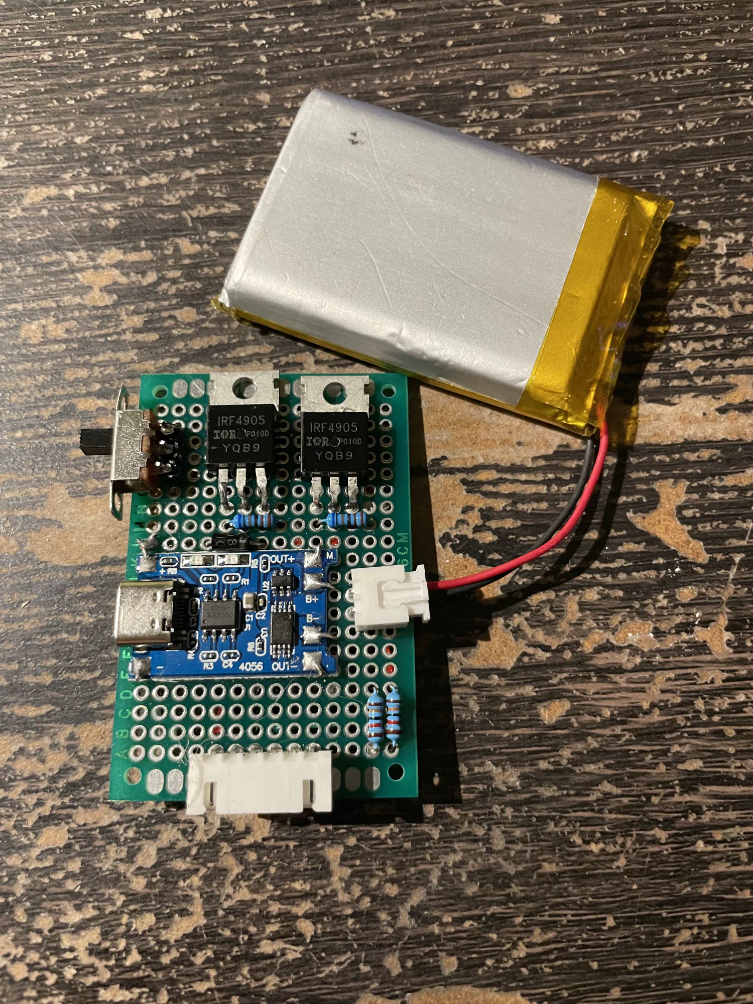
Skipping the schematics, I built it out on a protoboard, and despite misteps I was able to get the circuit fully functional. What this meant was that now, I could plug a cable into the USB port, charge the battery, and have the entire circuit run off of the USB power source. This is possible because, in it’s default configuration, the TP4056 will limit its draw to 1A, meanwhile most USB chargers are capable of putting out at least 2.1A. It’s very possible to go over that limit, depending on your use case, however I’m lucky enough to be able to limit the current draw using the firmware configuration, and thus comfortably fit within that envelope.
This is the stage where things started to get very good. This circuit is solid.
Iteration 5: Boosting to 12V, Noise, Capacitors, and a Better Way
This was an experiment. I had created a double-sided “halo” of 12V RGB LED’s that I found next to a dumpster. The controller was trash, however the lights still worked, and I was able to make a controller out of an Arduino. This was simple, basic, and very noisy. For controls I had 3 potentiometers, one each for Red, Green, and Blue, and at max draw it would surpass the capabilities of the 2.1A output of a 5V power bank.
That worked, but this is a new era, and I wanted to see what it was like using a more advanced microcontroller. Now, I’d previously attempted to use a boost converter to get a constant 5V from a Lithium battery, and found that the ESP8266 was unable to boot. Cheap boost converters are noisy, and while the humble Arduino is simple enough to run despite it, the same was not true of the ESP8266. Ultimately, I decided that it didn’t matter: boosting is a lossy process, and I value runtime. I also value beauty, which is why all of my products have made use of the SK6812 series of addressable LED’s. I’ve tested these between 3.3 and 5V, and found their performance to be quite satisfactory. The same is purportedly not true for the WS2812, or APA102 series of LED’s, which exhibiit a very noticeable degradation of their light quality as the voltage drops.
For this iteration, what I did was to power the ESP8266 from the Iteration 4 charging circuit, as well as the addressable light channels. In addition, I configured the noisy boost converter to output a 12V rail. This worked fine, while there was nothing hooked up to it, however once I connected the lights it became highly unstable.
I attempted to solve this using capacitors. In an ideal world, I’d have access to an oscilloscope, so that I could see exactly what the waveforms look like, and add capacitance to keep things tip-top throughout. I happen to live in the real world, though, and at this point had access to only one value of electrolytic capacitor, so that’s what I used. I added one to the 12V out, and it helped, however it was still not consistently stable. I added another to the 5V rail, and this got it working, although hilariously, I didn’t need an oscilloscope to see the noise in the waveform.
By this point, my products are audio responsive, meaning the lights bounce to the beat. What I found was that the LED on the TP4056 that indicate whether it’s charging, or the charge is complete changed colours in response to the beat. This is likely because the software that enables me to constrain the power consumption of addressable LED’s has no faculty to do the same for a string for analog LED’s. That’s a failure of the software, however it meant that it was completely impossible to reign in the power draw of the 12V LED’s. This didn’t APPEAR to cause problems, and I however the onus here being health & safety, I opted to cease using the analog 12V strip.
This version is still in operation, however it’s being used with a newer controller that isn’t capable of handling analog LED’s.
Iteration 6: Voltage Dividers, Useful Bits, and a Surrogate Relay
 At this point, I’m quite happy with the circuit, however it’s all about the details, and there’s a few left to touch.
- Voltage Dividers The ESP series of Microcontrollers contains the faculty to convert an Analog signal into a Digital signal. What this means is that, given the 3.3V operating/reference voltage, should you provide 2.5V to an analog input pin, it will be read as ~3103. This is because the ESP32 has a 12-bit resolution ADC. That’s cool, but my battery can go up to 4.2V, and that’s too much to send to any of the pins directly.
Luckily, there’s an old trick called a voltage dividor. Ther way that it works is that you take two resistors, in this case of the same value, connecting one to the voltage to be read. On the other side of that resistor, you connect it to the ADC, and you also connect that same point to ground through a resistor of equal value. What this achieves is to effectively “split” the voltage at that middle-point, so that half goes to the microcontroller, and half goes to ground. By using a large resistor, very little current is actually being drawn, and the voltage level is such that, with a small amount of processing, on the part of the firmware, the battery voltage can be read with a reasonably good level of accuracy.
There’s “better” ways to do this, however they’re not necessarily that much better. This can entail IC’s that can bring a whole lot more to the table, communicate over I2C, and provide a much more accurate reading. Nonetheless, this is a quick, easy, and reasonably effective solution. - Useful Bits Now, I mentined earlier about that 1.1A power budget left over after taking 1A to draw the battery. The question that I had was whether I’d be able to find some way to inform the microcontroller what the charge status is. Theory being, if the battery is charged, and we know it, then we can pull the whole 2.1A available from the supply. It turns out this is possible. On the TP4056 board, there are two LED’s that indicate charge status, and the way they are turned off/on is to switch the relevant pin on the IC between High-Impedence, and Ground.
What this means is that, were a line to be connected to that same pin, and then pulled up to 3.3V, it can then be read as a digital signal. If the pin reads LOW, that means that the LED is illuminated, and either it’s charging, or the charge is completed. If neither of those pins reads LOW, then that means their is no USB power supply connected, and operations are via battery power.
This is not entirely implemented, however when I look to the final version of this subsystem, it’s something I think carries a very big punch for its weight. It’s a very short logic table, and two additional digital pins, but with them an intelligent power management system can be programmed. This would enable for automatic switching between multiple modes of operation based solely on the present status of the charge system. Combining those two bits with the voltage of the battery itself should enable sufficient functionality to be considered, truly, “Good Enough”. - a Surrogate Relay I’m basing my products on the WLED open-source project, because it’s quite good, it saves me time, and it’s being actively worked on by a bunch of very smart, very passionate people. I Love Them. One thing they gave me was the ability to switch on/off a “relay” when the system power is toggled on/off. This doesn’t turn off the microcontroller, however the IC inside of each addressable LED draws ~1mA of current, even when it’s off. Given 80 lights in a hat, that means 80mA of draw, in addition to the draw from the microcontroller itself. Instead of a relay, I’m using another P-Channel Mosfet, with the gate being controlled by the digital pin set up to be a relay. When the power is on, the lights are on, but when the power is off, the lights are no longer exhibiting any draw. It’s a modest improvement, and a very easy win.
The Final Solution
I’m quite happy with this circuit, and it’s one I’d very happy to use going forward. That doesn’t mean that it’s perfect, however for the present use-case, it’s quite satisfactory, and it’s something I’m looking forward to having manufactured… so that I never need to solder one of these by hand again!
Right now I’m torn, as to whether to keep the power system modular, or if it should instead be incorporated into the main board. The bonus point for modularity is that, if it’s cheap enough to manufacture, I could actually market and sell it as a stand-alone product. I’m certain there are people out there who would love to pay an extra few dollars on a TP4056 if it nets them a solution that will solve virtually all of its major deficiencies… Namely, USB Pass-Through, voltage sensing, the ability to relocate those charge status LED’s, to read their digital value, and have a main power switch built-in.
The Future
There’s always more that can be done.
Capacitors
This is something missing from the current boards. I’m not getting major noise, but there’s noise, and the power draw from an ESP-type microprocessor is very spikey. Without an oscilliscope, or suitable equipment, it’s not possible for me to know with confidence the ways in which this circuit is lacking. I nonethless think that it’s a very fun-sounding prospect.
USB-PD
I picked up some USB-PD spoof circuits, and they’re wonderful things. It turns out that even the phone charging stating only 5V and 9V output will actually give 12V if you ask for it. Instead of boosting 5V, instead it could be bucked, and in the process it might enable supplying power to higher voltage LED’s. This brings about problems, when I’m working with a 3.7V battery, so it’s a stretch goal, and not presently in the cards, but nonetheless awesome, and a future direction.
User-Replacable Batteries
This one’s a stretch, because it adds another degree of uncertainty, greater liability, and the potential for user error. It’s probably better to have the entire system work within the constraints of a single battery, however batteries age, and being able to give the product new life could be a great boon. The question remains as to whether the lights, or the battery will fail first. So far, it’s the battery.
This might entail Lithium-Ion instead of Polymer, and that could potentially be a major problem, given my current set of constraints. The battery cutoff voltage being 2.9V means that, for most of the battery’s useful life, I can also get useful light out of it, using an SK6812. The cylindrical cells cut off around 2.4V, and that’s far below the needs of our microcontroller. It would likely require a series setup, or some other means of controlling the voltage. That’s a world of complexity that I don’t presently need.
The Moral of the Story
When I started this, I was scared. I attached the first battery using screw terminals, had no power switch, and seemed vaguely liable to explode. It didn’t help that I’d spoken to some older engineers, people who were scared of the kids on their lawn, insisting that I was a fool for using Lithium, and taht Nickel-Metal-Hydride was the superior choice. I think they were fools, on this note, however I’ve put an enormous of time, effort, and thought into ensuring that it is being done safely, because I genuinely give a shit about the health, safety, and longevity of those that I serve. Not everyone is as disciplined as I am, and it’s quite possible to do harm by taking short-cuts, and half-assing something important. This is something important, and that’s why I’ve gone the extra mile.
Because I Love You.